This guide is designed to provide installers with instructions on how to install Cisco MV cameras such that optimum results are obtained from EVERYANGLE applications used to analyse data from those cameras.
This guide provides general instructions on the positioning and adjustment of the cameras in question and the thinking behind them. It should be used in conjunction with, and not as a replacement for, the Cisco Meraki installation instructions that accompany the cameras. It also provides specific instructions on how to cater for a range of different physical characteristics at a customer site that may prevent the installation following the general instructions. However, it is not possible to anticipate every obstacle that may be encountered. If in doubt as to the positioning of cameras for a specific location, please log a support ticket by emailing support@everyangle.ai.
PROCESS STEPS
Below is the sequence to be followed in order to install Meraki cameras for the purpose of deploying EVERYANGLE applications.
-
. . . . . . . . Site survey
-
. . . . . . . . Order appropriate kit including mounting brackets if required
-
. . . . . . . . Configure dashboard and firewall following sections 9.0 & 10.0
-
. . . . . . . . Add the cameras to the dashboard.
-
. . . . . . . . Go on site and mount the cameras
-
. . . . . . . . Adjust the camera
-
. . . . . . . . Request deployment of the apps.
WHAT TO BRING WITH YOU ON SITE
-
Login details for the Meraki Dashboard so you can view the footage as you adjust the cameras.
-
A device, such as a phone, tablet or laptop to use to view the footage.
-
If you do not have a login to the dashboard then you will need to video conference with someone who has so ensure that your phone/tablet/laptop has the appropriate conferencing software installed such as Microsoft Teams or Webex.
-
A ladder appropriate to the height of the ceiling or wall to which the cameras are to be mounted. - Assorted basic tools
-
Assorted drill bits for concrete, wood and steel
-
A hammer drill if mounting on a brick or concrete surface
-
A battery-operated drill/screwdriver is useful as a time saver.
-
Cat5/6 cable and terminals for both ends
-
Wire strippers, a punch tool and crimper for terminating the cables.
-
Trunking/cable casing if required.
PHYSICAL INSTALLATION CONSIDERATIONS
Directional Cameras
The following is a list of EVERYANGLE products which are only compatible with Directional Cameras.
-
Footfall Footfall Intelligence
-
Visual Reidentification
These applications require that the cameras be trained on a defined entrance/exit such as a door or entrance to a passage or corridor. Analysis of the data from the cameras is set to take place as people walk through that entrance/exit and at that point only.
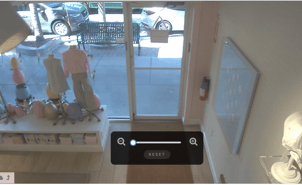
MV cameras may be mounted on a vertical surface such as a wall or door frame, or on a horizontal surface such as a ceiling.
Best results are obtained when the camera is mounted 3m (10ft) back from and at 90 degrees to the centre of opening such that people are generally facing the camera as they pass through the entrance/exist. The camera should be positioned low enough to pick up the faces of the people it detects and not so high that it mostly sees the top of their heads. A typical false ceiling has a height of between 2.3m (7ft 6in) and 2.45m (8ft) and this is perfect for the installation of a camera directly in the ceiling.
In this situation and assuming it is indoors, one of the MV12 or MV63 range is suitable and is the lowest cost option available but one of the MV22 or MV72 (outdoor models) will work also.

|
|
|
|---|---|---|
|
FIG. 1 - AS CAPTURED FROM A CAMERA IN AN IDEAL POSITION. |
|
FIG. 2 - AS CAPTURED FROM A CAMERA IN AN IDEAL POSITION NOTE THAT THE TOP OF THE DOOR IS AT THE TOP OF THE IMAGE AND THE DOOR IS VERTICAL |
INSTALLATION CHALLENGES
This is a list of challenges commonly encountered along with suggested solutions.
THE CEILING IS TOO HIGH
Solution
-
Fig. 3 below shows the range of options for the mounting of a fixed lens MV12W or MV63 before it becomes necessary to use one of the MV22 or MV73 range of camreas. If the angle of incline becomes too steep the accuracy of the results from the camera analysis decreases. The blue line in the diagram below is the limit above which the camera should not be mounted at any given distance from the door. MV12W’s may be used at any point within the mounting zone for the MV12 as shown. 5m is the limit of effective range for this camera model.
-
Once the range exceeds 4m it is necessary to use an MV22 which is good up to a range of 9m.
-
If you are faced with a situation which is outside the range of an MV22 you should confer with EVERYANGLE for advice on other options. It is possible that the 9m range may be exceeded depending on lighting and other environmental conditions or EVERYANGLE may advise the use of an MV22X. Advice will be provided upon examination of each unique situation.

FIG. 3 - IDEAL VERTICAL MOUNTING ZONES FOR MV12 MV22,and VM63 camera models
OBSTACLES ON THE GROUND
Challenge : There is a wall or other non-movable obstruction less that 3m (ft) back from the door to be monitored.
Solution Look for an alternative location. For example if, immediately after entering through the door in question, people have to turn right into a corridor which is narrower than 3m (10ft) then look to position the camera inside the corridor or pointing at the mouth of that corridor as people exit from it.
MULTIPLE ENTRANCES
Challenge: There are more than 1 entrances to be monitored.
Solution: Cameras need to be mounted at each entrance used by the public if total footfall is required. If total footfall is not required but rather the customer is interested mostly in demographic analysis then they may take the view that the demographic data they require will suffice if taken from the main or busiest entrance
CEILING OBSTRUCTIONS
Challenge: There is already something mounted to the ceiling in the ideal location that cannot be moved such as a light or air-conditioning vent. In this picture can be seen a ceiling obstruction (a ceiling fan) and a ground obstruction (a display table with product on it). The EVERYANGLE applications cannot work successfully in this scenario.
This blocks the camera’s view of the feet of people entering the store and this, in itself will prevent the successful operation of the EVERYANGLE application.
Preferred Solution: Look for a location further back and on the same line as the ideal location. If the first available point is more than 4.5m (15ft) from the entrance, then instead of an MV12W use an MV22. It has a variable focus lens and can be set to zoom in on the door from further back.
Alternative Solution: If a location is available that is less than 35 degrees off centre then position it there.
Fig 4. CAMERA MOUNTED AT AN ANGLE
Note that the further off centre a camera is positioned the less accurate the demographic analysis will be as this relies on a good view of a person’s face to perform the facial analysis.
THE IDEAL LOCATION IS OUTSIDE AND EXPOSED TO THE WEATHER
Challenge: There ideal camera placement will be exposed to weather
Solution: Use an MV72 camera. The MV72 range is an outdoor rated camera.
BELOW 0°C ENVIRONMENTS
Challenge The camera is to be installed in an environment where temperatures below zero degrees Celsius (32 Degrees F) can be expected.
Solution Use an MV72 camera as it has an inbuilt heater to protect it from frost and freezing conditions.
CAMERA ADJUSTMENT
Once the camera is mounted in a suitable location the next step is to adjust the field of view of the camera. The camera lens may be turned through 180 degrees and it may be tilted upwards and downwards. Remove the lens cover to make these adjustments. If you need to swivel the camera more than 180 degrees then you will need to remove it from the surface to which is it mounted, turn it through 180 degrees before remounting it and then complete the fine adjustment on the camera.
To complete this step you will need to view the footage from the cameras either by logging into the dashboard yourself or by videoconferencing with someone else who is logged in.
Cameras trained on doors should be adjusted so that:
-
The sides of the door frame are vertical in the picture and the top is horizontal to the ground.
-
The top of the picture is just at the top of the door frame. We want the top of the door frame to be visible but there is no point in including space above the door where there is nothing to be analysed.
-
If using an MV22 it should be zoomed in such that the door fills as much of the picture as possible.
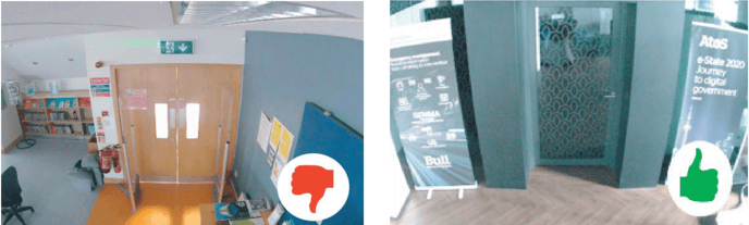
FIG 5: TOO MUCH CEILING VISIBLE FIG 6: EXAMPLE OF IDEAL CAMERA
ABOVE THE DOOR ADJUSTMENT
360 Degree (Fisheye) Cameras
The following is a list of EVERYANGLE products which are only compatible with 360 Degree Cameras.
-
Engagement Analysis
-
Queueing analysis
- Associate Not Present
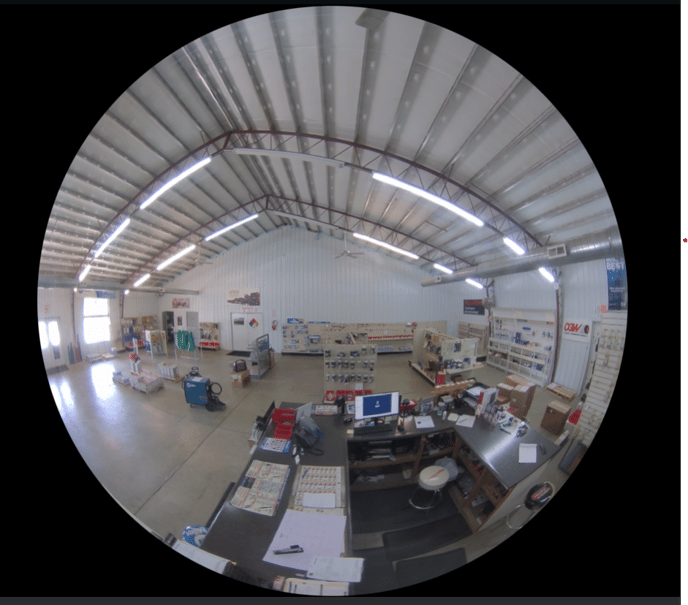
Because of their 360 degree field of view, the positioning of these cameras has much more tolerance than is the case with directional cameras. The higher the ceiling the more tolerance there is.
If one were to draw a circle on the ground surrounding the area of interest for the application in question then the camera should be positioned as close as possible to the center. A few feet in any direction is not normally an issue.
.png?width=688&height=603&name=image%20(1).png)
FIG 7: IDEAL LOCATION FOR FISHEYE CAMERA FOR THE ASSOCIATE NOT PRESENT APPLICATION
Note that how camera is positioned so that it has a good view of each side of the trade counter.
INSTALLATION CHALLENGES
Examples of common challenges encountered along with suggested solutions.
VAULTED CEILING
Some locations may not have a ceiling but instead a vaulted roof such as shown in the photo below.
Mounting the Fisheye camara on a vertical surface such as a wall as was done in this case is NOT A VIABLE SOLUTION to the problem. The lens of the camera must be facing downwards towards the target area. There are extension poles available from Meraki but if these are not suited then it will be necessary to have them purpose-made.
CEILING OBSTRUCTIONS
If there are any obstruction to the field of view of the camera that would obscure the camera view of persons in the zone of interest then those obstructions should either be removed or, failing that, the camera should be moved to a position that minimizes the impact of the obstruction so long as the new position is not outside the zone of interest. Any situation where placing the camera towards the edge of the zone of interest should be referred to EVERYANGLE for approval.
MOUNTING LOCATION IS OUTDOORS OR IN AN AREA SUBJECT TO TEMPERATURES BELOW FREEZING
Use a model from the MV93 range of outdoor fisheye cameras.